Thanksgiving Turkey vs Jet Engine: A Smoothed Particle Hydrodynamic Approach to Model Bird-Strike
- Aventec

- Oct 30, 2020
- 9 min read
Updated: Nov 5, 2020
By Hicham Farid, PhD CAE/FEA Engineer at Aventec

Introduction
In the aerospace industry, a bird-strike generally refers to a collision between an airborne animal (bird or bat), and an aircraft. Every year, tens of thousands of bird-strike accidents are reported, although less than 5% of these accidents could be considered as damaging strikes. The monetary cost-related is estimated to be more than $1.2 Billion.
Bird-strike prevention is considered a top safety priority by many airline pilot associations. As simple as it might sound, a bird flying towards a jet engine at landing or take-off could cause serious damages to the engine’s integrity, sometimes causing a loss of power, altitude, and an airplane crash.
When testing a new engine during development stages, jet engines manufacturers must comply with the standards established by both the Federal Aviation Administration (FAA) and the European Union Aviation Safety Agency (EASA). Although these standards are similar, they are not harmonized, therefore new engines must meet both requirements. To address these requirements, manufacturers must put the engines through physical testing to ensure the structural integrity of a jet engine in the event of a bird-strike. Physical testing is generally very complex and very expensive as engines must be tested for various bird sizes in different thrust regimes.
The bird-strike physical testing program involves firing an actual bird into a running jet engine and determining the engine’s damage. An effective way to increase the efficiency of test programs is to perform numerical simulations. A high-fidelity numerical model means that the engine design can be optimized prior to the actual final stage of physical testing, saving many resources on the way.
In this paper, inspired by thanksgiving and my love for jet engines, I performed a bird-strike simulation using a full-size high bypass jet engine and an actual turkey model. The dynamic nature of the bird-strike as well as the high deformability of the bird at impact make the classical Finite Element approach limited, hence the choice of the Smoothed Particle Hydrodynamic method.
Background: Smoothed Particle Hydrodynamics
The bird strike test is a highly dynamic problem. Studies have shown (Heimbs) that the classical Lagrangian framework is incapable of yielding reliable results. The high deformity of the bird during the strike suggests that other modeling techniques can be used with more efficiency to model the impact of the bird with the fan blade of a jet engine. The Smoothed Particle Hydrodynamics addresses these modeling needs with ease.
Lagrangian Approach

Eulerian Approach

Arbitrary Lagrangian-Eulerian (ALE) Approach

Smoothed Particle Hydrodynamics (SPH) Approach

Figure 1. Different modeling approaches
Before diving into how to implement the SPH technique and moving forward with the bird strike simulation, I want to give a quick overview and comparison of different finite element methods that could be considered for this class of problems.
In Figure 1, I tried to present an intuitive schematic that illustrates the difference between the aforementioned -mentioned techniques. Within the Lagrangian description, which is usually the method of choice for structural analysis, the nodes of the model move exactly with the material points. It is more intuitive within this framework to track the free surfaces and apply different types of loads and boundary conditions. However, the downside of this method is that the mesh becomes more susceptible to distortion when facing high strain gradients.
As opposed to the Lagrangian description, in the Eulerian framework, the nodes of a spatial mesh stay fixed while the material flows through. It is difficult to track free surfaces in an Eulerian description, but there is no issue with mesh distortion as the mesh is fixed in the space. The Eulerian approach is available within Abaqus/CAE using the Couple Eulerian-Lagrangian (CEL) capability.
Within Arbitrary Lagrangian-Eulerian (ALE) approach, the mesh motion is restrained to the material only when necessary, mainly at the free boundaries, otherwise, the material motion and mesh are independent. This approach minimizes the mesh distortion while maintaining the same mesh topology.
The Smoothed Particle Hydrodynamics (SPH) approach addresses modeling needs where other classical methods fail or are inefficient. Violent fluid flows where classical CFD cannot cope such as shallow water flows, or extremely high deformations such as ballistics and snow compaction where CEL is difficult/impossible to implement are examples where SPH can be used with a high level of efficiency.
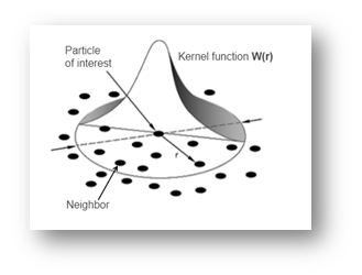
Figure 2. Kernel function
The Smoothed Particle Hydrodynamics method’s novelty lies in a specific method for smooth interpolation and differentiation within an irregular grid of moving macroscopic particles. Since the nodal connectivity is not fixed, severe element distortions are avoided, hence the method allows for very high strain gradients.
The SPH method is simply a discretization method of continuum partial differential equations rather than a method that models the interaction (contact) between different particles (like with the Discrete Element Method or DEM). The method uses an evolving interpolation scheme to approximate a field variable at any spatial point.
Going through the mathematical formulation and the basics of the method implementation is out of this paper’s scope. I can refer the reader to “Smoothed Particle Hydrodynamics Code Basics” by J.J Monaghan, as well as the Abaqus Documentation.
Smoothed Particle Hydrodynamics in Abaqus
The SPH method is an Abaqus/Explicit capability that can only be implemented for 3-D models only. The SPH particles are defined using one-node PC3D elements, these particle elements use the existing functionalities of Abaqus to reference element-related features such as material definition, loads, and boundary conditions.
Activating SPH particles can be achieved using two different conversion techniques; particles can be generated per parent element, or particles can be generated based on a uniform background grid.
The conversion technique from a finite element mesh to particles per parent element is usually used when high strain gradients are expected, such that the classical elements deletion techniques of severely distorted elements are limited. The number of particles generated per parent element can be controlled as well as the conversion criteria. Four different conversion criteria can be specified based on the nature of the simulation; Time- based, Strain-based, Stress-based, and User Subroutine-based. This functionality is available through Abaqus/CAE through the mesh module under the Element Type control menu.

Figure 3. Internally generated particles per parent element illustrated for three particles per isoparametric direction
Generating particles based on a uniform background grid method is intended to generate a uniform distribution of particles at the beginning of the analysis. This method is useful for applications where the uniform distribution of particles is desired such as when modeling fluids. The origin of the background grid is placed at the center of the mass of the element set to be converted. The finite elements in the set are converted to SPH particles at the beginning of the analysis. The particles are generated only at grid line intersections that are inside the volume of a parent element. All generated particles have the same volume and mass. Any parent element that does not contain a grid intersection has no generated particles associated with it.

Figure 4. Internally generated particles based on a uniform background.
In this paper, I will be using the first method to convert a finite element mesh to particles. I will be using a time-based criterion for the conversion.
Getting the Turkey Ready
Before diving into the model setup, I would like to talk a little bit about the impactor geometry for bird strike simulations. Knowing that there is no standardized artificial bird shape (Heimbs), various geometries can be found in the literature. Different shapes are typically chosen to reflect the mass and the geometry of a bird’s torso. The main geometries found in the literature are cylinder, a cylinder with hemispherical ends, ellipsoid, sphere.

Figure 5. Different substitute geometries for the bird during a bird-strike simulation
For this paper, I used the real geometry of the bird during this simulation, which is a Turkey in this scenario. The Turkey model was obtained through a real turkey scan, an .stl file was obtained after that. CATIA was used to generate a CAD file for the Turkey model. The turkey model was then imported into Abaqus/CAE.

Figure 6. The Turkey 3D Model
I meshed the Turkey model using C3D4 elements (4-node linear tetrahedron). When selecting the mesh element type, I toggled yes from the Conversion to particles submenu as shown in Figure 8. I selected a conversion method based on time and selected 0 as Threshold, which means that all the elements from the Turkey model will be converted to particles at the beginning of the first step’s increment.

Figure 7. Meshed Turkey Model

Figure 8. Element type selection and element conversion to particle definition
I also chose a PPD of 1, which is the number of particles to be generated per isoparametric direction. The SPH model is shown in Figure 9.

Figure 9. Converted model to SPH Particles
The general assumption is that the bird is mostly composed of water. The general framework of elastoplastic material models or even hyperelastic material models seems to be limited. Therefore, it is much common to use an equation of state (EOS) for the constitutive model of a bird. The EOS presents a relationship between the pressure and the volume of the bird impactor with the parameter of water at room temperature. Common equations of the state include linear, polynomial, tabulated, and the Mie-Grüneisen. I used the laser equation of state definition within Abaqus/CAE, which also specified the linear difference between shock velocity to the velocity of the particles to define the Hugoniot pressure.
[Equation] (Us− Up)
To recap, material parameters for the Turkey model include the mass density, as well as the EOS parameters which include c0 and Γ0.
Jet Engine Model Preparation
A dummy turbofan jet engine model was prepared for the bird-strike simulation. Figure 10 shows an iso view and a side view of the engine. The main objective of this paper is to show the proper implementation technique of the SPH method rather than providing any engineering insights. However, the material parameters as well as the simulation boundary conditions were picked to the nearest realistic scenario based on my own literature research.
New engine fan blades are generally made of titanium alloy Ti-6Al-4V, which is an alpha-beta titanium alloy with a high strength-to-weight ratio and excellent corrosion resistance. The high dynamic effect of the impact dictates the consideration of the strain rate effect on the fan material. The summary of the used material parameters of the fan is tabulated in Table 1 and Table 2.

Figure 10. Iso view and side view cut of the dummy jet engine
In order to make the simulation lighter, I used a Display Body constraint and restrained the simulation domain to the fan only (highlighted in Green in Figure 10).
Table 1: Material properties for titanium alloy ( Lesuer, 2000).
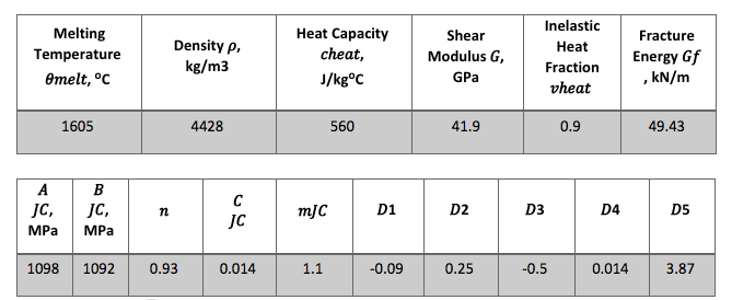
Table 2: Johnson-Cook damage parameters for titanium alloy (Lesuer, 2000).
Bird Strike Model Setup
As mentioned above, only the fan was considered a continuum body during the simulation, the rest of the jet engine was modeled using a display body constraint with No motion. A coupling constraint was added to restrain the fan rotation to those of a reference point located at the center of the main shaft. A rotational velocity boundary condition was then applied to this reference point using a Predefined Field. The chosen Angular velocity was 41.88 radians/second.

Figure 11. Iso view of the Turkey-Jet engine assembly

Figure 12. Zoomed-in view of the Turkey with the fan blades
An initial impact velocity of about 400 mph was applied to the Turkey. I used a general contact approach with frictionless formulation to model the friction between the Turkey and the fan at impact. The simulation was run using Abaqus/Explicit for 0.01 s or 10 ms. The impact angle between the turkey and the fan was 90o.
Results
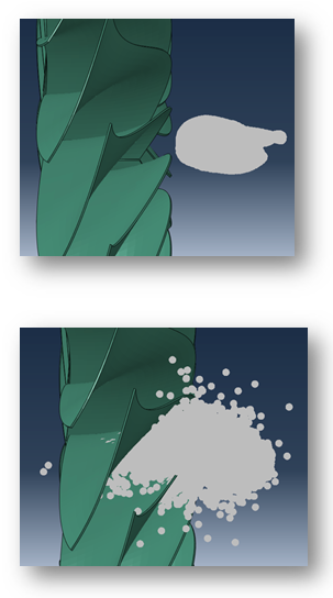

Figure 13. Impact progression from top-left to bottom-right (0 s, 2.5 ms, 5 ms, and 7.5 ms)
As mentioned above, the Turkey finite element model was converted to SPH particles at the beginning of the first increment. The impact between the turkey and the fan blades happens while the fan is rotating.

Figure 14. Von Mises and Pressure stresses distribution on the fan
Most of the impact happened on the fan blades, generating a local stress of 155 MPa approximately, as well as a local pressure of 31 MPa. However, this specific model setup did not generate any local plastic deformation at any of the impacted blades.
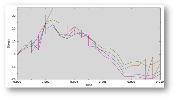
Figure 15. Pressure stress evolution versus time
Figure 15 shows the evolution of the pressure stress during and immediately after the impact. This shows an immediate increase in stresses right at the impact, then a decrease as time evolves. The model’s kinetic energy shows a similar trend.
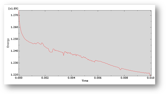
Figure 16. Model’s kinetic energy
The model’s kinetic energy decreases significantly with time as the model is predominantly governed by the bird’s velocity. We can see that there is a significant decrease of kinetic energy at impact as it gets transferred to the fan blades in the form of strain energy.

Figure 17. Model’s strain energy
Summary
A bird-strike analysis was performed in this paper.
The Smoothed Particles Hydrodynamic method was chosen to perform this kind of simulation
Internally generated particles per parent element method was used to convert a finite element mesh into SPH particles
A time-based conversion criterion was used to convert the FEA mesh into SPH particles
Special Thanks
Special thanks to my colleague Mr. Steve Hotchkiss from the CATIA team for helping with the Turkey model. The Turkey model was obtained through a real turkey scan, an .stl file was obtained after that. Steve performed the conversion from an .stl file to a more useful CAD format.
References
FAA, Fact Sheet – The Federal Aviation Administration’s (FAA) Wildlife Hazard Mitigation Program, July 27, 2020
Heimbs, S., Computational methods for bird strike simulations: A review, Computers and Structures 89 (2011) 2093–2112
Husainie, S. N., Bird Strike and Novel Design of Fan Blades, 2017, Science in the Age of Experience.
Monaghan, J. J., Smoothed Particle Hydrodynamics Code Basics, Journal of the Korean Astronomical Society, vol. 34, no. 4, pp. 203-207
Lesuer., D. R., Experimental Investigations of Material Models for Ti-6Al-4V Titanium and 2024-T3 Aluminum, Federal Aviation Administration, DOT/FAA/AR-00/25, Livermore,
2000


Comments